With all the different kinds of tools available to help you do your job, the ones that make things faster and easier are the most useful. For machine service technicians, one of those tools is JLG’s 3-D hydraulic schematics. But many machine service technicians need help with how to read hydraulic schematics.
Designed to help troubleshoot machine hydraulic issues on JLG® boom and scissor lifts, as well as JLG and Skytrak® telehandlers, this interactive tool allows you to view 3-D renderings to locate and trace a hydraulic circuit to its function, quickly and conveniently. And the best part? If you need to order a replacement part, you can do that right from the schematic.
Let’s walk through JLG’s 3-D hydraulic schematics, following these four steps to get a better idea of how to read hydraulic schematics.
Step 1: Find the exact machine you are looking for
Once you are signed into Online Express, go to the Service tab, which is the second tab over and down, and click on “3-D hydraulic schematics.” Here you can choose the equipment type you want to look at. For example, when you click on boom lifts, you will get a listing of all the JLG models available. You can also search for equipment schematics by a machine’s serial number and the PVC code.
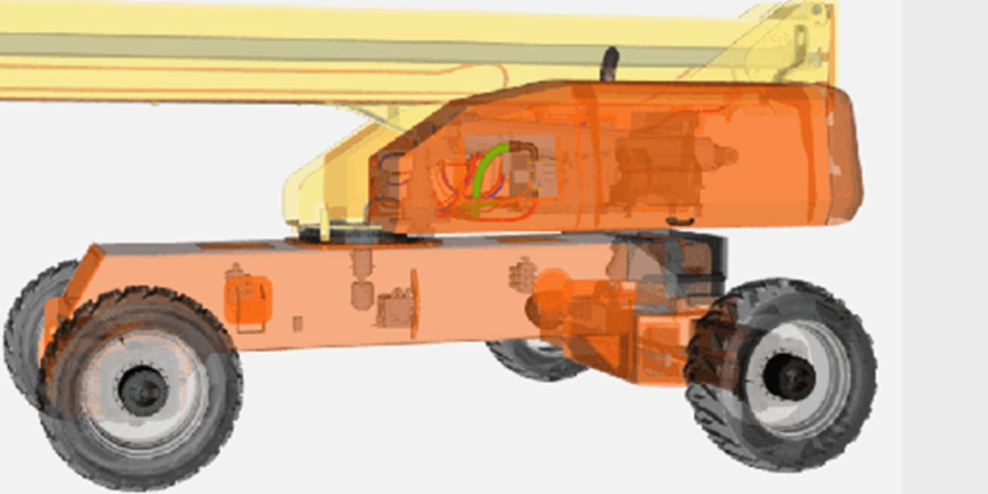
To access a particular machine’s schematics, select the model you want, such as the 520AJ, and click on “view schematics.” The page will populate with a 3-D rendering of the unit you chose.
Here’s an example of what you will see on your screen:
Step 2: Select the hydraulic lift schematic components you need to troubleshoot
Once you have found the machine you’re looking for, you can drill down to see the exact components you need to take a closer look at. But how do you drill down into the hydraulic lift schematic to find what you need?
Here’s how: On the left-hand side of the screen, select which components to show or hide to be able to view the hoses and connectors, as well as anything else that you would like to see. For example, if you are troubleshooting the ground control panel, you can hide the hood, so you don’t see those components simultaneously.
Once you select the component you want to view, such as the function for ground control, the schematics will pop up, showing you all kinds of different flows, the suction, the pump, the return and even the electrical input for the machine’s solenoids. There will also be a legend of all the different hoses within the circuit.
There are tools available on the right-hand side of the screen to adjust how you are viewing the rendering. For example, you can make the model transparent or solid, depending on your preference on how best to see these hoses and connections.
This is an example of how the machine’s components will be highlighted in the schematics for easy viewing:
Step 3: Get a closer look at every component
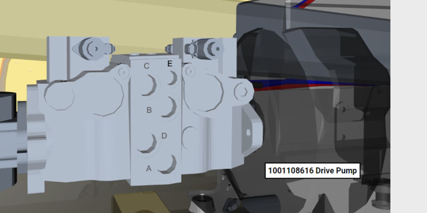
You can also click on any component area in the hydraulic lift schematic to expand your view. And, you can quickly move your view around, zooming in and out as desired.
Here’s an example of how it would appear on your screen:
There are different ways to move the machine based on if you're using your computer’s mouse controls or if you're using the keyboard and tracking pad. For example, simply double-clicking in the center of the component you want to see will pull the image into the center of your screen. Depending on your preference, you can also change the speed at which you are viewing the schematics, slowing down or speeding up.
Also, if you click on the “swing left” or “swing right” commands, you’ll notice that as the function populates, so do those specific components associated with it, color-coded depending on where they are located. This will really help if you've got to change hoses, especially on JLG machines where there are a lot of hoses like our scissor lifts, where it becomes more beneficial to see not only where those hoses are but also which ports they go into and then come out of.
Step 4: Click to order replacement parts
And if you need to replace a component, like one of the hoses you were looking at, a part number for each part associated with that component is listed, with a brief description, by simply scrolling over the item. If you click on the part number, it will be added to your shopping cart on
Online Express and ready for you to order!
Another option within the schematics is to click on the “manual” tab and be able to find all the manuals (Operation & Safety, as well as Service & Maintenance and Parts) of the machine you are looking at. Having all of this information in one place means that you will be able to access the information you need as quickly and efficiently as possible.
Step 5: Login and get started
JLG 3-D hydraulic schematics are available to anyone with access to Online Express. If you don’t already have an account, you can request a login here to gain access. Once you receive login details, sign in to get started.
If you still have questions on how to use these schematics? Watch the “JLG 3-D Hydraulics Schematics Troubleshooting” tutorial video for a quick rundown of how best to use this feature by clicking here.
Do you want to stay up to date with industry news and issues similar to this? Make sure you subscribe below to receive monthly updates from #DirectAccess with newly posted content, so you never miss important information.